Tolerances for thermoformed plastic parts
Precise, reproducible, and cost-effective: how to define the right tolerances for your thermoformed plastic part
Why are tolerances so important in plastic deep drawing?
During the manufacturing of formed parts, slight dimensional deviations can occur due to one-sided tool contact, material thickness variations in the blanks, and internal stresses within the material itself. Adhering to the maximum permissible tolerances is crucial, especially for technical formed parts and automation trays.
Function-oriented tolerance design in thermoforming
As a rule of thumb, the tighter the necessary tolerances, the more expensive the tools and manufacturing costs will be.
ℹ️ For the creation of your formed parts, we rely on function-oriented tolerance design. Based on the requirements you submit in the configurator, we derive the functions of the formed part. These functions are then described in the drawing with the necessary references and tolerances. After your review and approval, the manufacturing process begins.
Influencing Factors
Material: Plastic
Plastic parts have greater dimensional variations than metallic materials due to their lack of rigidity and high deformability.
- Despite advanced manufacturing techniques, processing is often empirical
- Key dimensional properties: Rigidity, hardness, processing shrinkage
- Warping can lead to deviations in shape, position, and angles, making standardization more difficult
- Variations in molecular weight between material batches affect flow behavior and processing shrinkage—fluctuations in industrial-grade material can be significant
- Deformation and flow behavior impact dimensional accuracy
Production-Related Dimensional Changes
Dimensional deviations may occur due to:
- Processing shrinkage variations
- Incorrect tool shrinkage compensation
- Different elastic recovery behavior
- Tool deformation and wear (standard steel dimensions: ±0.01mm)
Application-Related Dimensional Changes
Production-related length deviations can occur due to:
- Climate influences
- Mechanical deformations (external forces, relaxation of internal stresses)
- Operational energy exposure (e.g., heat in engine compartments)
- Diffusion contact (vapors, liquids)
- Material removal (friction)
- Molecular structure transformation
General Tolerances
Limit Dimensions for Linear Dimensions
DIN ISO 2768-c
| Tolerance Class | Limit deviations in mm for nominal dimension range in mm (always +/-) | ||||||||
|---|---|---|---|---|---|---|---|---|---|
| DIN ISO | 0,5 - 3 | >3 - 6 | >6 - 30 | >30 - 120 | >120 - 400 | >400 - 1.000 | >1.000 - 2.000 | >2.000 - 4.000 | >4.000 - 8.000 |
| 2768-c | 0,2 | 0,3 | 0,5 | 0,8 | 1,2 | 2,0 | 3,0 | 4,0 | 5,0 |
All linear dimensions are subject to DIN ISO 2768. Standard deep-drawn parts fall into tolerance class 2768-c (see table):
DIN ISO 2768-m
| Tolerance Class | Limit deviations in mm for nominal dimension range in mm (always +/-) | ||||||||
|---|---|---|---|---|---|---|---|---|---|
| DIN ISO | 0,5 - 3 | >3 - 6 | >6 - 30 | >30 - 120 | >120 - 400 | >400 - 1.000 | >1.000 - 2.000 | >2.000 - 4.000 | >4.000 - 8.000 |
| 2768-m | 0,1 | 0,1 | 0,2 | 0,3 | 0,5 | 0,8 | 1,2 | 2,0 | 3,0 |
All linear dimensions are subject to DIN ISO 2768-1. On request, deep-drawn parts can be manufactured to tolerance class 2768-m (see table). However, we must first check and approve all tolerance ranges for deep-draw manufacturability.
Tolerances for Holes and Openings:
- Molded part: 0.5mm
- Hole diameter: 0.13mm for holes smaller than 25mm
- Hole diameter: 0.25mm for holes between 25 and 125mm
- Slots: 0.25mm for slots smaller than 25mm
- Slots: 0.5mm for slots between 25 and 125mm
- Milling: 0.5mm for holes larger than 125mm
Thermoformable features you should pay attention to
Plastic thermoforming is a complex process with many variables that can influence tolerances. By observing these rules, errors in CAD design and in the end product can be avoided.
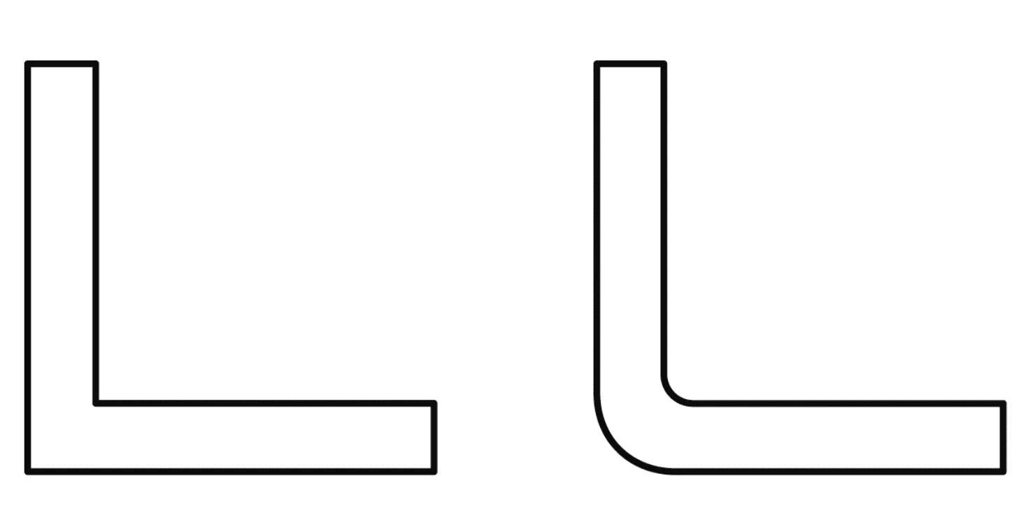
Corner and Edge Radii
A minimum radius of 1.5mm is required. Larger radii are recommended to improve material stretchability.
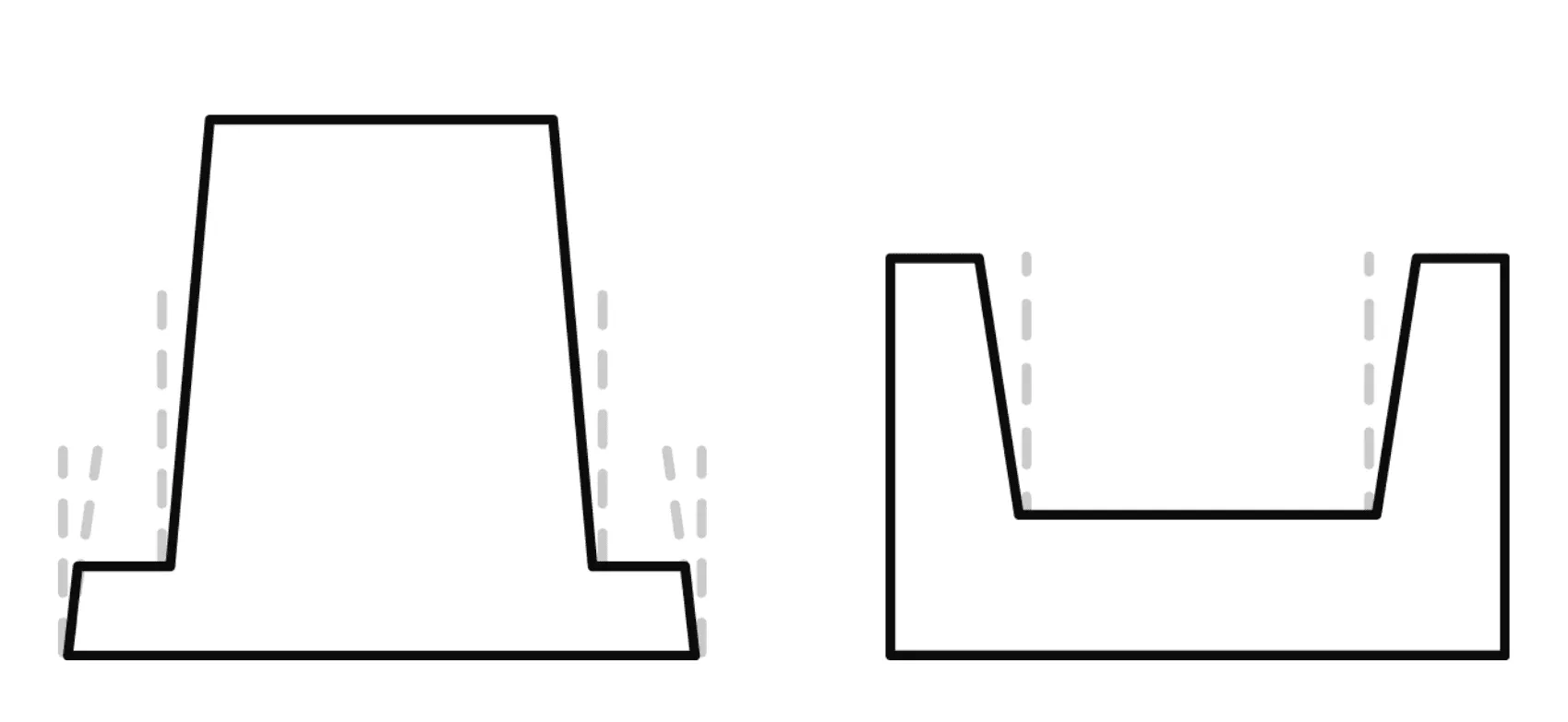
Wall Angles
A wall angle is always necessary to ensure demolding.
✓ Negative molds: Minimum 1.5 - 2°
✓ Positive molds: Minimum 4 - 6°
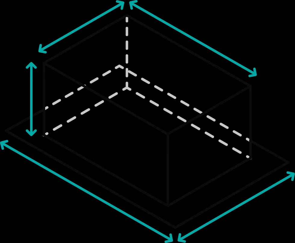
Forming Ratio
Wall thickness varies along the formed part due to material stretching. The resulting thickness can be estimated using specific formulas.
ℹ️ You can calculate the expected wall thickness in advance, or enter details in the configurator, and we will determine the necessary starting material thickness.
Further information on design & tolerances in thermoforming
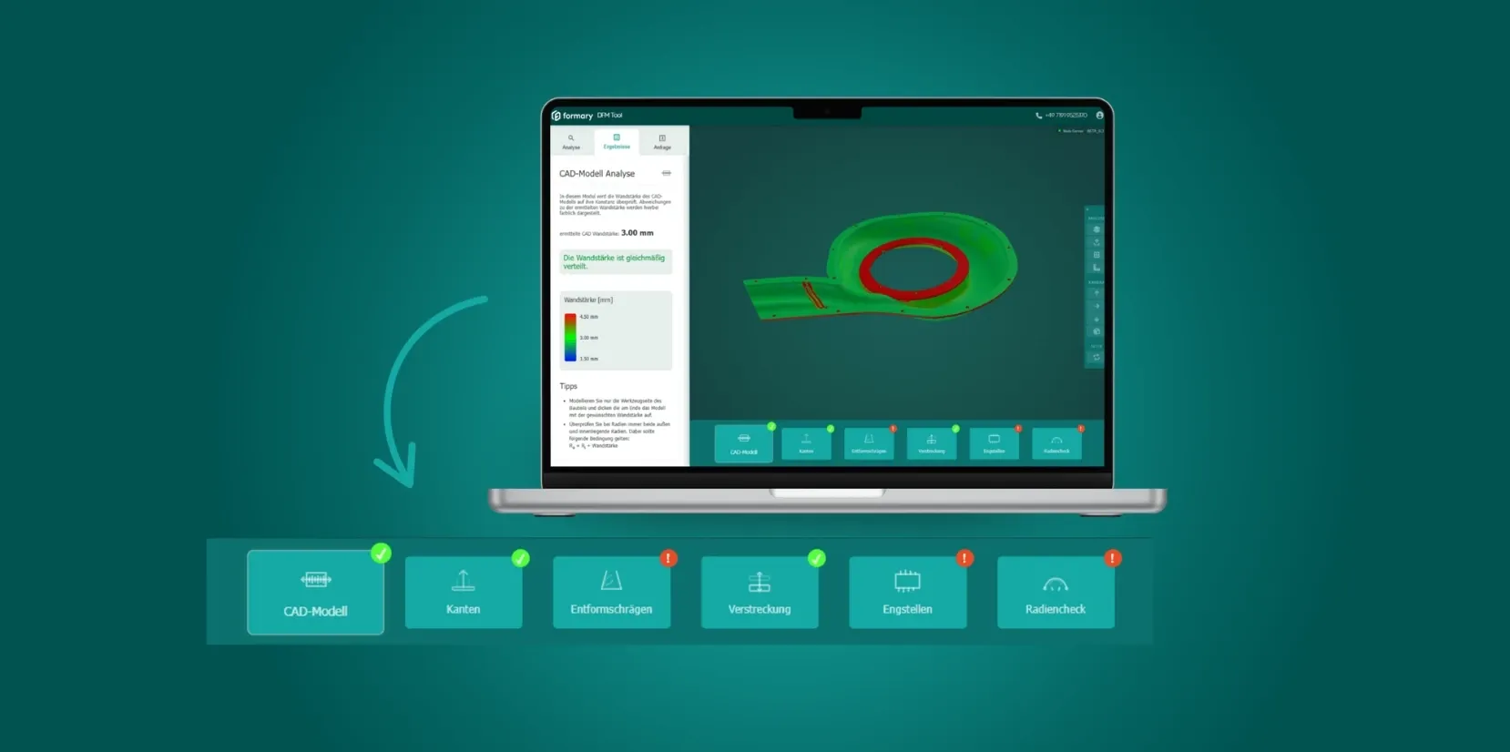
Design rules for thermoformed plastic parts
Read our article to learn which design rules you should follow when manufacturing thermoformed plastic parts in order to ensure thermoforming-capable tolerances.

Design guide for thermoformed plastic parts
In our thermoforming design guide, you will find not only design rules for thermoforming-friendly components, but also information on the thermoforming process, materials, and more.
Frequently asked questions about tolerances in plastic thermoforming
Plastics expand more and react to temperature and humidity, which is why tolerances in thermoforming are larger than those of metal parts.